Tip No. 11
Now, pay attention to this next one...
One of the main purposes of a page layout program and what differentiates it from modern wordprocessors that allow compositions using text and graphics (like Microsoft® Word) is that a page layout program allows precise placement of text and graphics. Oftentimes, you may find yourself repositioning lines by themselves or groups of lines and other objects.
The following examples show the difference in the coordinates in the Measurements palette when a line is selected vs. when a line plus another object is selected. Knowing how Quark™ handles this and other such subtleties can make the difference between making a professional or an amateurish layout.
In the example below, a horizontal line having an 8-point thickness is selected. Notice the y-coordinate in the Measurements palette (78 pt).
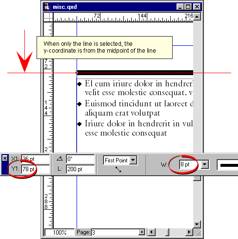
Next, Shift-Click to select the text box with the line. Notice how the y-coordinate in the Measurements palette has changed from 78 points to 74 points. Why is this? When a line is selected by itself, the Measurements are made from the midpoint of the line (see Tip No. 4). However, when a line is selected as part of a group (or a multiple selection), the measurements are made from the outside edge of the line.
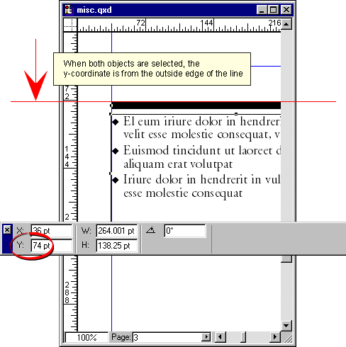
In this case, there is a difference of 4 points from outside edge of the line to the midpoint of the line because the line width is 8 points. This is a noticeable difference, but with lines having smaller widths (such as 1-point) you may or may not notice that something is not right with your layout. The principle extant here applies to vertical as well as horizontal lines, so x-coordinates can be affected as well.
Tip No. 12
By now, some of you may realize how to use the principle in the previous tip to create lines with mitered corners. Following is the step-by-step procedure:
| 1. Draw first line and snap to guide. 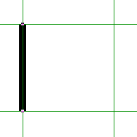 | 2. Draw text box and select it and line together then drag until edge of line snaps to guide. 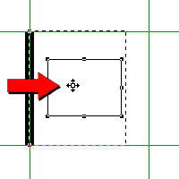 |
| 3. Draw second line and snap to guide. 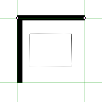 | 4. Select it and text box and drag until edge of line snaps to guide. 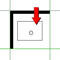 |
Tip No. 13
For picture boxes containing grayscale or true color images (RGB or CMYK) and which do not use clipping paths, set them up with a white background. Do not set them up with a background color of "None". The reason is that Linotronic imagesetters and other high-end output devices cannot differentiate the edges of the image from the background. The background pixels need to be mapped like any other pixel in the image. Click here to setup the picture box creation tools so all picture boxes have a white background by default.
Output results of picture box with a white background... 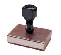 | Output results of picture box with a background of "None"... 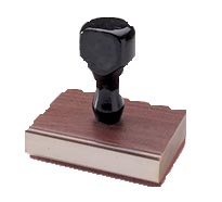 |
Notes:
a.) The background color of a picture box containing a black and white (1-bit) image can be set to "None".
b.) If a clipping path is used, version 4.x of QuarkXPress will automatically set the background to "None".
c.) If you are using a clipping path with an earlier version of QuarkXPress, the image must be an EPS file saved with a clipping path and you have to manually set the background color of the picture box to "None".


 3:24 PM
 Unknown
0 comments:
Post a Comment