Showing posts with label Cinema 4D Tutorial. Show all posts

Monday, March 21, 2011

BASICS, FACES AND THE BRIDGE TOOL

This Basics tutorial is to explain how to build faces and the three uses of the bridge tool that make it very very useful!!!! Creating faces using the CREATE POLYGON tool is accurate and used most often but can be slow at times, the BRIDGE tool allows you to fill in faces very quickly, you can also bridge gaps between two parts or cut a clean hole through an object..Read on!

BUILDING FACES

OK first off create a new polygon object as shown, it will just be a blank object ready for points and faces to built into it.

 1. click POINT MODE, 2. make sure your on the MOVE TOOL, 3. HOLD down CTRL and left click in a window to add points. This allows you to start adding points that the faces will be built from..... 


  1. Still in POINT MODE, 2. Click STRUCTURE and 3. select CREATE POLYGON, this sets it in face building mode 

 OK to build faces you click CLOCKWISE, 1,2,3,4 and 5 back to the first point to create the face, (if you build the faces anti-clockwise they will face the other way) Its also better to build quads (two flat triangles that make up a four sided poly) as its better for smoothing etc afterwards, but you dont have to and sometimes you cant :) tri's are OK here and there but try to work in quads. You can also select say 1-10 (for example) points and it will build all the faces how it thinks its best to but I prefer to control exactly where I put the faces.... 

 The other thing I wanted to mention was to Untick (turnoff) DISABLE BACKFACE CULLING, this is vital so you can see which way faces are facing, if they are facing away they are invisible (shame you cant colour backfaces??) anyway its best to work mainly in this mode especially for lowpoly modelling otherwise when you export the model you'll find it has holes (faces facing the wrong way) etc.....OK onto the faster way of building faces...THE BRIDGE TOOL


THE BRIDGE TOOL - PART 1 - BUILDING FACES

 OK same again, 1. create a new polygon object and add some points using CTRL and click, 2. select STUCTURE, 3. and select the BRIDGE TOOL or instead just press "B" to enter BRIDGE mode. 

 OK click and hold 1 and drag to 2, click and hold 3 and drag to 4. WOW instant face now carry on dragging from bottom to top and you can whack in a load of faces in a few seconds, press ESCAPE (to break off face building) when you get to the end and start from the beginning of the next row below and fill in another row of faces, very fast way of building faces this is. If I had dragged from top to bottom the faces would have faced the other way.....


THE BRIDGE TOOL - PART 2 - BRIDGING A GAP

 OK the next thing the BRIDGE tool can do is join to things together. 1 I created 2 boxes and made them EDITABLE, I then selected them both and 2. clicked CONNECT to join them into one object, this creates a new object, so select the original seperate two objects and delete them leaving the single object made of 2 boxes....the objects have to be CONNECTED (not joined) to bridge the gap between.... 


1. OK in FACE mode, 2 I selected the two inner faces and 3. press K to use the KNIFE tool and 4 and 5 I KNIFED two lines here to create some more detail on the inner faces. 6 as you can see here both boxes are in one object... 

1. Still in FACE mode I selected the 2. two faces I wanted to BRIDGE between and I also select 3. XRAY mode so we can see through it...also when I switched off DISABLE BACKFACE CULLING ealier well that needs ticking back on again otherwise you cant see the backfaces :)

 OK click and drag from 1 to 2 as shown and there you go the gap is bridged and inner faces get autodeleted, it doesn't have to be square can be any shape although I think both ends of the bridge need to be identical....not sure gotta try that out :)


THE BRIDGE TOOL - PART 3 - CUTTING A HOLE

 OK the third thing the BRIDGE tool can do is create a hole through an object sometimes a lot cleaner than a BOOLEAN. 1. select FACE mode and select both sides of a box, 2. KNIFE across to get it divided up... 

 1. Still in FACE mode select just the faces at the end on both sides, 2. press "I" to EXTRUDE INNER and drag it in a bit. 

 1. Faces still selected in FACE mode, press "B" for the BRIDGE tool and drag from 2 to 3 to instantly create a hole through the object. 4 also tick XRAY before you do all this so you can see where to drag from and to!! 

I dropped it into a HYPERNURBS object and you can see its smoothed with a hole through the end, as you can see the BRIDGE tool has many uses!! I hope you guys out there find this stuff useful, if you do stop by http://www.psionic3d.co.uk and drop by the forums with the rest of us 3D/4D maniacs ;)

Friday, March 18, 2011

UV UNWRAPPING AND PAINTING A GUN IN BODYPAINT

Heres the REFERENCE PIC of the gun in case you want it!


This first part of the tutorial is going to deal with a quick efficient way to UV map a weapon in BODYPAINT, it may seem a bit daunting at first but after while you'll rip a gun to bits in 15 minutes!! The concept behind it is to seperate each group into front,back, sides, top and bottom then lay them out efficiently and finally paint the skin itself, wanna know more? read on...

 1. First off make your model, and as you can see here its in several groups because it will later be animated for in-game use, recoil and reloading etc, 1. Click the Layouts button 2. and Choose BP UV EDIT to go into UV EDIT mode....and 3. Click here if there is already a texture there to enable painting on it, if not I'll be showing you how to create a new texture later...


OK we are gonna start with the barrel so select it and 1. Click here to go into FACE MODE, 2. then choose the SELECT TOOL, 3. RIGHT CLICK and choose SELECT POLYGON and 4. SELECT ALL and this will select all the polys in the barrel group

 1. Make sure the barrel is selected and 2. Click the UV MAPPING tab and PROJECTION and choose BOX mapping and as you can see its box mapped the barrel!!

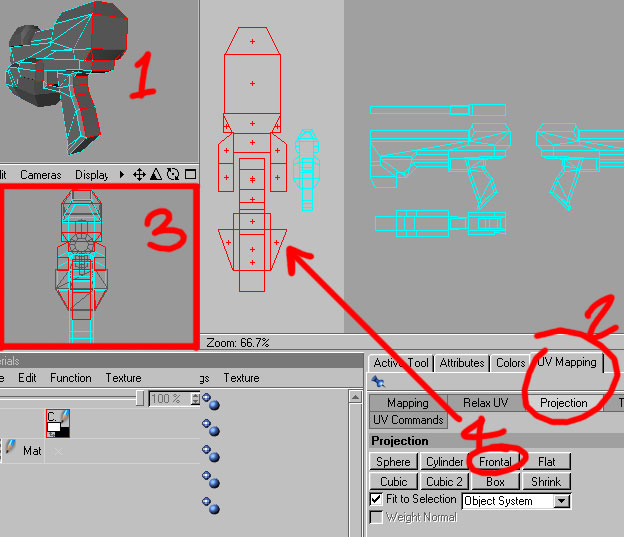
 1. Still in UV mode and using the SELECTION TOOL and SHIFT to ADD to what faces are selected and CTRL to MINUS from the currently selected faces, 2. We select all the end faces of the barrel and the inner faces because they are all gonna be mapped from the front.

 1. Choose UV MAPPING and PROJECTION and 2. Click FRONTAL, BUT before you do make sure 3. the FRONT VIEW is active as marked, Frontal maps from the currently active views' angle even the 3d camera (USEFUL) 4. As you can see its a bit squashed so choose NON-UNIFORM SCALE and stretch it horizontally a bit!

 After arranging the top and sides a bit better it seems they are flipped horizontally so 1. Choose UV MAPPING and 2. UV COMMANDS and 3. select the faces and Click MIRROR U to flip them!!

 After flipping them to match 1. We move the top over the bottom and 2. the Side over the other side now it needs rotating by 90 degrees so click 3. TRANSFORM and 4. Type -90 degrees and click APPLY...

 Heres what we end up with 1. Top/bottom view 2. Front view and 3. Sides view. After a bit of arrangment they are all nice and efficient, wasting no space and its obvious which parts are which! This is the basic principle, select and box map, move like parts over their equals (flipping if needed) and use FRONTAL mapping from the appropriate view and the SELECT, MOVE, SCALE tools as well to organize....Easy ;-)

 Onto the main part, looks daunting but its the same technique!! Ok 1. Select "main" and select all faces as before and 2. Choose UV MAPPING AND PROJECTION and 3. choose BOX mapping and as you can see it all gets laid out, it always needs a bit of tidying up/organizing so thats what we do next...

 1. Select the back faces (make sure you get em all because some get mixed up in the box mapping) and 2. Choose UV MAPPING and PROJECTION and 3. Make the front/back view active then 4. Click FRONTAL mapping and as you can see the backward facing faces get mapped from the front/back view.

 1. As you can see the front faces of the grip are overlapping the front faces of the gun so 2. Select the faces to move and Click the MOVE TOOL and 3. Move em out from under to the side as shown so it gets its own UV space.

 Back to the side UV's and select one side ready for flipping....


1. Click UV MAPPING and UV COMMANDS and 2. Click MIRROR U as before and move it directly over the top of the other side.

 Heres all the UV's after Moving/Scaling/Rotating etc 1. The Front faces 2. Top faces 3. Side faces 4. Front of the grip 5. Bottom faces and 6. the back faces. The back faces are scaled up a bit because in-game you will see the gun mainly from the back/side so they have a bit more UV space! Easy wasn't it? ;-) Box map, Frontal map various bits, move/scale/rotate to lay them out efficiently...


Onto the next part the recoil block thingy on top, 1. Select all forward/backward facing faces 2. As seen here, make sure 3. The front view is Active and 4. Choose UV MAPPING and PROJECTION and 5. Click FRONTAL to map those faces


1. Make the SIDE VIEW Active and select the side faces and again 2. Click UV MAPPING and PROJECTION and 3. FRONTAL map the faces from that view. As you can see they are layed out as well, Front, sides and top/bottom...

 1. For the clip we can hide all the other objects by double-clicking the top dots for each one and this hides them in the viewports, 2. UV mMAPPING and PROJECTION and guess what? 3. BOX mapping!!!

 1. Select all the top faces after box mapping, 2. UV MAPPING and PROJECTION, 3. Make the TOP VIEW active and 4. FRONTAL map it from the top view.


Here it is all layed out, 1. Top, 2. front/back, 3. Sides and 4. Bottom face, 5. All done using frontal mapping from the appropriate views!

 Now we have to put all the UV's in the main UV Space square, Only the UV's of the currently selected object show up though ;-( one solution is to connect all the objects together then they will all show up, but for this one we are using guesswork ;-) basically all the main parts fit in the bottom half leaving 1. This area blank which we place all the other parts in, switching between to make sure none are overlapping!!

 If there is no material click 1. FILE and 2. NEW MATERIAL in the materials tab and this will create a new material, who woulda thought it eh? ;-)


1. RIGHT CLICK and 2. Choose TEXTURE CHANNELS and 3. Choose COLOR...see next stage..

 1. Make sure NEW TEXTURE is ticked, 2. Set the width/height in this case 1024x1024 and 3. Pick a base colour! Click OK and you have a new blank base image for the skin.


Now we need this material on each object so 1. Drag onto 2. "barrel" then HOLD CTRL and Click and drag this material onto the next one down, etc until they all have the same material, now its time to get painting, part 2 will be online very soon!! Any questions on anything C4D related drop by my Forums in the Cinema 4D section and I'd be happy to help!!

An Alternative Cartoon Render Technique


As we all know, the cartoon renderer in Cinema4D XL v6 leaves a lot to be desired. There's no control over line thickness, or solarizing amount, and some shapes just look flat because the lines are only drawn around single objects. You can try to overcome this by writing your own shaders, but I discovered a technique that allows for a whole lot more control without any special plugins or shaders. This is a pure Cinema4D, out-of-the-box technique. Hope it helps some of you.


create a shape

For the render to show anything, you do of course need some object in the scene. I just built a quick hypernurb object with some overlapping shapes and wrinkles to have a good idea how the technique reacts to these kind of shapes. As you probably know, the built-in cartoon renderer only draws a line around a single object, so any surface irregularities don't receive the oh so neccesary line.

 add a camera and a light
This technique relies on a light at the exact location of the camera, so you need a camera in your scene! Add one, and set the editor view to the camera. Next add a light, link it to the camera and use the coordinates manager to set it's position and rotation to 0,0,0. The light is now at the position of the camera and pointing forwards. You can move it a tiny bit behind the camera so the light's 'geometry' (the white asterix-type lines) don't obscure your view.
Now the fun starts.


creating the lines The spot you just added is the 'lines' spot. It will take care that each object receives a black line, by casting a shadow from the point of view. Because it is soft, the shadow will be slightly larger than the object that casts it. This results in a black 'glow' around the object that can be made into a line with some tweeking. This technique does mean that you have to have an object behind each object, else the line will not appear. So the first thing you do now is add a sphere that encompasses the whole scene. A sky object won't work, because it doesn't recieve shadows. Just add a very large sphere.
Next, turn your light into a spotlight. An omnilight would mean you need 6 shadowmaps where the spot only needs one. And as the light is connected to the camera, you'll never be able to look outside of the light's cone anyway. Also set the inner angle of the spot [details tab] to some value. Now you can control the 'iris' of the whole image by just pulling the points of the spotlight, allowing for some very nice effects.


Okay, so we need a soft shadow on the light. Set it's shadow to soft, and use a mapsize of 1000x1000 [shadow tab]. Lower resolution maps will result in thicker lines, but will also show more artifacts. In the shadow tab, set the light's bias to 1%, uncheck absolute (don't know why, but this setting seems to work best for this technique). If you get very dreadfull self-shadowing or smearing, just turn up the bias in slight amounts. Remember you do need a low bias if you want even tiny irregularities in the surface of the object to show up as lines.
Because we want this light to only create the lines around an object, and not to actually light it, turn on 'ambient illumination' [details tab] and just to be sure turn on 'no specular' as well. This doesn't have any effect, but I'm a supersticious guy :).
Now make a test render.


Ain't that interesting! We have some lines! But you must admit, they aren't too well defined ... wait a minute, what about that 'outline shadow' option? [shadow tab] Turn it on and make another test render.

Ah, that's more like it! If we now add a fully white material to the object and the background, instead of the default 50% grey, we get a very nice black-and-white drawing, with varying line thickness. Also, lowering the shadow map size increases the line thickness, though also the vague-ness. Lowering the shadow's 'sample radius' makes the lines less vague but show more artifacts - resulting in ragged lines which actually can look kind of nice!

 he settings of this image: shadow map 300x300, sample radius 1.

shading
We only have an outline now. How about adding some shading, to define the form some more? You could of course just add some lights and make the object non-white, but that would also mean that the shadow-lines would get less prominent in places where there is a lot of light. No, we need to do something else, namely add a negative light to create the shading. Add a light and set it to distant type [general tab]. I do this so I can keep the light object itself in the view of the camera and define it's angle by simple rotation. Rotate it so that it 'lights' the bottom of the object. In the details tab, set it's brightness [details tab] to -50%.


That looks almost like there is an actual light in the left top corner! Now, make a test render to check out the details.

 Hm, yes, well, nice, but we want a more cell-color like edge to the shading, don't we? Okay, let's turn up the contrast of the light [details tab]. The following image has a contrast of 120%. Higher values give you a more defined edge, but tend to flatten the image a lot as well. I personally kind of liked this well-defined but still gradiated look, as if it was colored with watercolor. I also turned 'down' the negative brightness to -20%.

 One pitfall to look out for, is that the bacground sphere will be rendered with the same contrast setting. In the image above, the light is pointing forwards by an amount large enough that this will not be a problem, but if you're less lucky you might get this:


You can solve this by using a different kind of light, like a spot or a parallel spot, so that the negative light doesn't reach the background. Another fix suggested to me was to add a render tag to the sphere, and set it to 'Compositing background'. This way the sphere will only catch shadows, and not lighting. You'll lose the 'iris' effect, of course, but who needs that :).


highlight So how about a small highlight? We'd need to color the object first of course, so first add some colored material to the object. Also give the material a well defined highlight (maybe even 1000% strength), so the final rendered specular will have that same solarized effect as the rest of the object. Add another light, set it to distant (for the same reasons as mentioned above), turn on 'no diffuse' (details tab) and rotate it so that the highlights are in the right place. Render.


That's about it. For this final image, I also gave the 'shadow' light a slight red/orange color. Because it is a negative light, this results in a blue shade on the object.


pitfalls I know this technique will not work in all circumstances, and there are a few pitfalls. For example, a highlight will blow away a line if the two meet. This can look kind of nice actually, but there's nothing you can do about it. Also, surfaces that are almost perpendicular to the camera (ie you look along the surface) can show the tendency to have a fair amount of self-shadowing, smearing the lines in ugly patches. This can to some extent be solved by turning up the bias, though that would also mean some lines will get less prominent. Anyhow, it's a nice technique, and can just as well be used on already existing scenes without changing any materials. You'll need to redesign the lighting of course, as that's what makes up this look.


and finally A final thing to try is to render a scene that is set up this way with ... the built in cartoon renderer! The lines will be even more defined while still retaining that varying line thickness. You'll loose the wonderfull watercolor-effect though.

Twitter Delicious Facebook Digg Stumbleupon Favorites More

 
Powered by Blogger