Introduction
When surface and edge modelling has been completed and the lighting has been setup correctly, materials can then be assigned to surfaces and edges. Different strategies are used for large unit paving (flags), small unit paving (tarmac) and edge material (kerbs following the edge of a road)
Download Sample Data
In order to follow this tutorial, you may want to use the supplied files. Please read the
sample data instructions before downloading.
AutoCAD Drawing files:
dwg_files.zip (784kb)
3ds Max Scene files:
scene_files (7.8mb)
8.1 Surface materials
- Carry on from the previous scene or open ACAD to 3D Stage 8.max
Tarmac, Grass and Bound Aggregate
- Open Key 3D View Manager and select View: Overview SW. Press Copy to Camera
- In the User viewport zoom to a section of the road
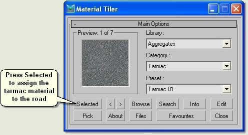
- Select B_Road Surface
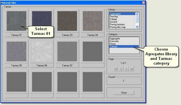
- Open Key 3D Material Tiler
 and press Browse
- Choose Aggregates library and Tarmac category
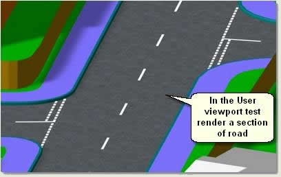
- In the User viewport zoom to a section of road and test render to view the results
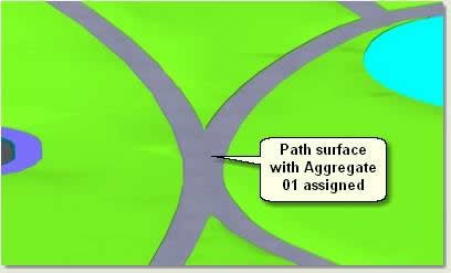
Next, the paths running through the park area require a bound aggregate texture
- Exit sub-object mode and Exit Isolation
- Using Key 3D Material Tiler assign Aggregates / Aggregate / Aggregate 01 to the paths surface: Surface Path
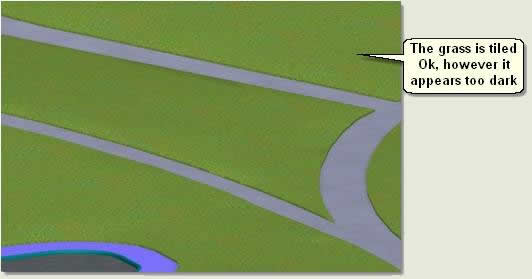
- Select Surface_B_Grass and assign Ground / Grass / Grass 01 to the grassed areas
The grass is a little dark and needs to be lightened slightly
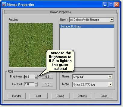
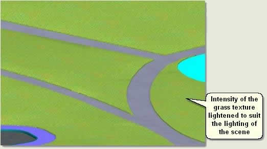
- Keep Surface _B_Grass selected and open Key 3D Bitmap Properties. Change the RGB Level to 0.8. This lightens the intensity of the grass texture to suit the lighting conditions
- Open the [Houses] group and change colour of houses to brick colour and roofs to a dark grey
- Close the [Houses] group
- Open the [Play surfaces] group and assign Aggregates / Aggregate / Aggregate 07 to Surface_B_Play02 (the smaller play surface)
- Assign Aggregates / Aggregate / Aggregate 07 also to Surface _B_Play01 (the larger play surface)
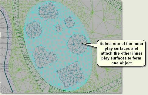
- In the Top viewport and in Wireframe display mode Attach the inner play surfaces together and rename Inner play surfaces
- Assign Aggregates / Aggregate / Tarmac 02 to the inner play surfaces. This has a similar texture to rubber safety surfacing
- Close the [Play surfaces] Group
Flag Paving
- In the Top viewport zoom to the pavement shown below
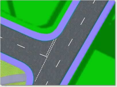
- Assign Paving tiles map / 600x450 / 600x450 run buff to Surface_B_Pavement
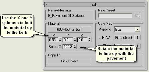
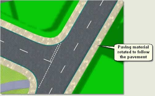
TIP: To make all sections of paving follow the direction of the pavement, split the paving up into sub-surfaces using the Key
3D Surfaces routine and assign a separate paving material to each section, rotating the paving material for each section
Site surface and Context surface
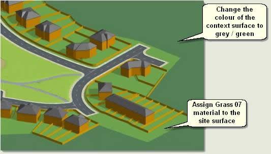
- Assign Ground / Grass / Grass 07 to Surface_B_Site
- Change the colour of Context surface to a darker grey/green
8.2 Fence materials
House fences
- Assign Fencing / Wood / Wood 10 to O_Fence
This material will appear too light
- Use Key 3D Bitmap Properties to reduce the RGB Level to 0.5 (Ref: 8.1)
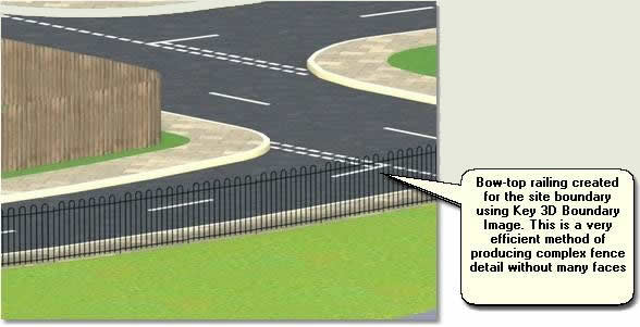
Create park boundary and play area fences
- The park and play areas boundaries require bowtop railings and these are created automatically using Key 3D Boundary Image. The following exercise explains how to create a boundary image for the park boundary. Firstly, Key 3D Edge Path is used to create a spline around the edges of the park surfaces:
- Select Surface_B_Pavement and Isolate Selection
- Open Key 3D Edge Path

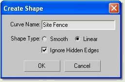
- Press Create Path and on the Create Shape dialog select Linear and type Site Fence in the Curve Name text box
- Exit Isolation and select Site Fence and Surface_Path
- Isolate Selection again
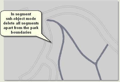
- Select Site fence path and enter Segment sub-object mode. Delete all segments apart from those on the park boundary. Also delete segments at entrance points on the park boundary spline
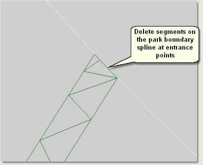
- Again, in Segment sub-object mode delete segments on the park boundary spline at entrance points
TIP: To speed up the process of deleting long sections of splines delete segments at either end of a longer section of spline, enter spline sub-object mode and delete the long spline section all at once
- Use Shape Check utility to check for any intersecting vertices and Weld any vertices that are intersecting
- Select Site Fence
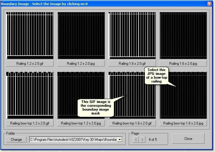
- Open Key 3D Boundary Image

- Press
 to open the following sample browser and navigate to page 4
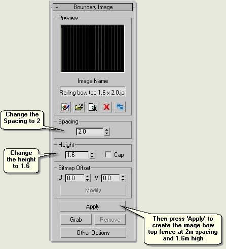
- Select Railing bow top 1.6 x 2.0.jpg. This must be the JPG file and not the GIF file (this is the image mask)
- Change the Spacing to 2
- Change the Height to 1.6
- Press Apply to create the image bow-top fence at 2m post spacing and 1.6m high
- Finally, select Site Fence and open Key 3D Bitmap Properties

- Make sure the bow-top jpg image is displayed in the preview window and change the Brightness to 0. This will make the fence darker and it will render better
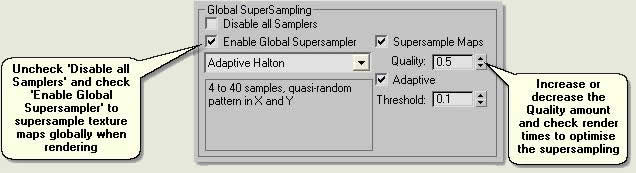
NOTE: Supersampling for this fence material will improve the rendering of the railings further (global supersampling is explained later in 'Rendering')
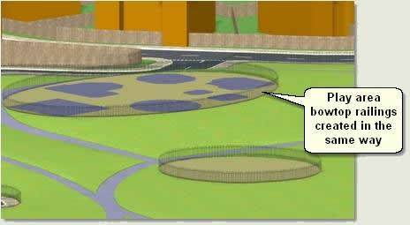
- Repeat the above routine for the play area fences and name these Small Play Fence and Large Play Fence
NOTE: The play area surfaces need to be ungrouped (or opened) before selecting the larger play area surface. Also, make sure no isolated vertices exist on each surface by using
Remove isolated Vertices in vertex sub-object mode
8.3 Kerb material
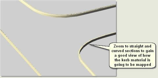
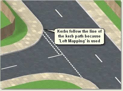
The kerb was created using the MAX/VIZ Loft compound object. This requires the material to follow the loft path, as real-world kerb sections follow the line of the road. The Loft mapping parameters are used to do this
- Select Loft01 and rename Kerb
- Zoom to the kerb loft to gain a good view of straight and curved sections
- Open Key 3D Material Tiler and assign Paving Tiles Map / 450x450 / 450x450 stack grey to the kerb
- On the Modify Panel remove the UVW Map modifier
- Open the Material Editor and select an empty sample window
- Use the Pick Material from Object button
 to pick the kerb's material for editing
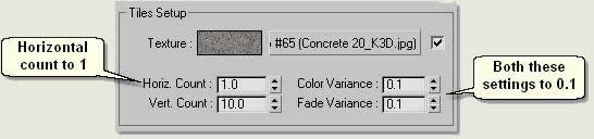
- Go to the Map level by pressing the Map Button to the right of the Diffuse swatch and open the Advanced Controls rollout of the Tiles material
- Change the Horizontal Count to 1
- Change the Color Varience and Fade Varience both to 0.1 and Go to Parent
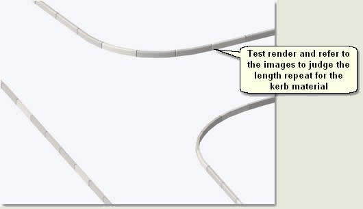
- In the Modify Panel Loft Surface Parameters change the Surface Parameters > Mapping, whilst viewing the kerb in the viewport and test rendering as below:

- When satisfied with the kerb mapping convert the loft to an Editable Mesh
- Exit Isolate Selection
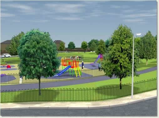
8.4 Sky background
- Maximise the Camera viewport
- Open Key 3D View Manager and select View: Entrance 01. Press Copy to Camera
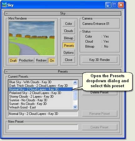
- Open Key 3D Sky. Press Presets and select Normal Sky - 2 Cloud Layers - Key 3D
The Mini-Renderer displays a small render of the scene via the current view selected in
Key 3D View Manager
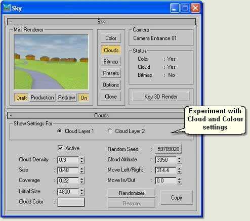
- Use the Colour dropdown and Clouds dropdown to change the sky and cloud properties:
TIP: Make the
Cloud Layer 2 altitude higher than
Cloud Layer 1 and slightly darker. Use subtle
Cloud Density so that the sky does not detract from the main scene elements. Use a preset for a good start and tweek settings to get the desired result or press
Randomizer to obtain a random start. When happy with a sky solution save it as a preset for future use in any scene
- Close Key 3D Sky
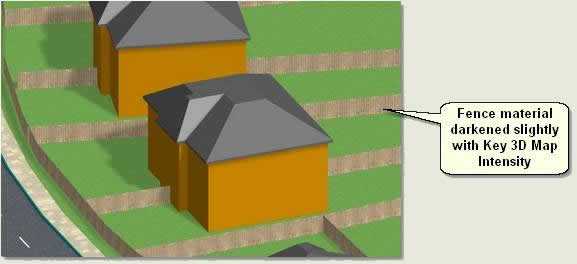
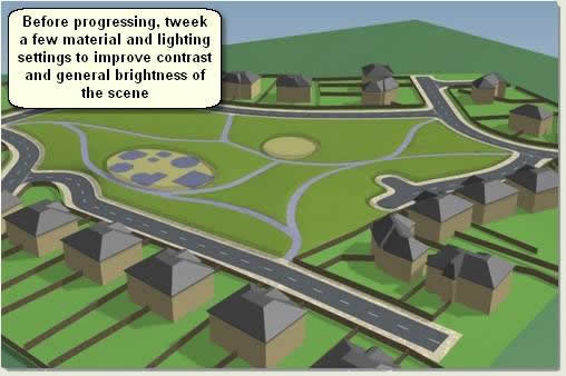
- Finally, tweek the colour of the Houses by opening the group and selecting all the houses. Also, tweek the Bitmap Properties of the grass (slightly darker) and house fences (slightly darker)
- Tweek the shadow settings in Key 3D Sunlight and perhaps decrease the Light Dome multiplier to 0.4


 2:51 PM
 Unknown